You’ve got a great design. It looks perfect on screen. Every dimension is exactly where you want it, every feature meticulously placed. Then you send it to a CNC shop and they come back with questions you didn’t expect—or worse, they quote you 3x what you budgeted.
I’ve been on the shop floor for over 30 years. I’ve seen designers make the same mistakes over and over. Not because they’re bad engineers—because nobody ever told them how a CNC machine actually cuts metal. This CNC machining design guide is the conversation we should have had before you hit “send” on that CAD file.
Here are 10 design for manufacturing rules that will save you money, time, and a lot of embarrassing emails.
Quick Reference: The 10 Rules
| Rule | Key Number | Why It Matters |
|---|---|---|
| 1. Standard tool sizes | 6mm, 8mm, 10mm, 12mm | Avoids custom tooling costs |
| 2. Wall thickness | Al 0.8mm / Steel 1.2mm | Prevents chatter and breakage |
| 3. Cavity depth | ≤ 4× tool diameter | Prevents tool deflection |
| 4. Internal radii | As large as possible | Enables faster, cheaper machining |
| 5. Threads | M2 min, ≤ 3×D depth | Reduces machining time |
| 6. Side features | 3‑axis if possible | Fewer setups = lower cost |
| 7. Tolerances | ±0.1mm standard | Tighter tolerances = 2–5× cost |
| 8. Finishing | Account for anodizing growth | Prevents out-of-tolerance parts |
| 9. Text | Flat surfaces only | Avoids slow 3D engraving |
| 10. Fixturing | Design for standard vises | Minimizes setup time |
Rule 1: Design for Standard Tool Sizes
Every CNC shop has a rack of end mills. At MachMaster, we keep a full inventory of standard tools—6mm, 8mm, 10mm, 12mm, 16mm, and 20mm diameters. We can grab any of these off the shelf and start cutting.
The moment you design an internal radius of 3.7mm, you’ve just forced us to order a custom tool. That means waiting days and paying 2–3x the cost of a standard tool. And for what? A radius that could have been 3mm or 4mm.
Bad: Internal corner radius of 3.7mm in a cavity.
Good: Internal corner radius of 4mm—a standard 8mm end mill cuts it perfectly.
The general rule: design your internal radii to match standard end mill diameters divided by two. If you’re using a 10mm end mill, your minimum internal radius is 5mm. Use the largest radius you can—larger tools are more rigid, cut faster, and cost less per part.
Rule 2: Mind Your Wall Thickness
We see this mistake weekly. A designer specs a beautiful thin-wall enclosure, and our machinist takes one look and says, “This is going to chatter like crazy.”
Thin walls vibrate under cutting forces. The tool deflects. The surface finish looks like a washboard. And sometimes, the tool just snaps.
Here are the numbers we use at MachMaster:
| Material | Minimum Wall Thickness |
|---|---|
| Aluminum | 0.8mm |
| Steel | 1.2mm |
| Titanium | 1.5mm |
| Plastics | 1.5mm |
Bad: A 0.5mm wall in aluminum to save weight.
Good: A 1.0mm wall in aluminum—still light, actually machinable.
If you absolutely need thinner walls, we can do it. But we’ll have to slow down feeds, use smaller tools, and take lighter cuts. That adds time. Time is money.
Rule 3: Avoid Deep, Narrow Cavities
Here’s a rule of thumb: cavity depth should not exceed 4× the tool diameter. If you’re using a 10mm end mill, that means your cavity should be no deeper than 40mm.
Go deeper, and the tool starts to deflect. The cutter wants to wander. Surface finish suffers. Tools break.
Bad: A 6mm-wide slot that’s 50mm deep.
Good: A 6mm-wide slot that’s 24mm deep (4× diameter). Or widen the slot to 12mm so we can use a bigger, stiffer tool.
At MachMaster, we can do deeper cavities with specialized long-reach tooling. But it costs more and takes longer. We’ll always tell you upfront during our free DFM analysis.
Rule 4: Add Radii to Internal Corners
This is one of the most fundamental CNC design rules, and designers still get it wrong.
A CNC end mill is round. It cannot cut a sharp 90° internal corner. The corner will always have a radius equal to the tool radius.
If you design a pocket with sharp internal corners, here’s what happens: we either use a tiny end mill (slow, expensive, fragile) or we send it to EDM (very expensive).
Bad: A square pocket with 0mm radius internal corners.
Good: A pocket with 3mm radius internal corners—machinable with a standard 6mm end mill.
The larger the radius, the larger the tool we can use, the faster we cut, and the cheaper your part gets. A good target is an internal radius at least one-third of the cavity depth.
Rule 5: Keep Threads Realistic
Threads are one of the most over-specified features we see.
Minimum size: M2 is the smallest thread we recommend. Below that, taps break constantly.
Blind hole threads: Add at least 3mm of unthreaded relief at the bottom of the hole. The tap needs room to run out, and chips need space to accumulate.
Thread depth: Don’t spec threads deeper than 3× the diameter. There’s no functional benefit—the fastener will fail before the threads strip. Going deeper just adds machining time.
Bad: M2.5 thread, 10mm deep, in a blind hole with no relief.
Good: M3 thread, 6mm deep (2× diameter), with 3mm relief at the bottom.
Rule 6: Consider Undercuts and Side Features
If your part needs features on the side—holes at an angle, undercuts, complex contours—you’re looking at 4‑axis or 5‑axis machining.
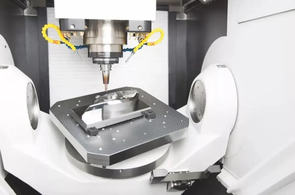
At MachMaster, we run 5‑axis machines daily. We can handle complex geometries. But 3‑axis machining is always cheaper.
Bad: A side hole that requires the part to be repositioned three times.
Good: A side hole positioned so it can be reached in the same setup.
If you can rotate the feature to a 3‑axis orientation, you’ll save money. If you can’t, we’ll do it on a 5‑axis—but we’ll tell you the cost difference upfront.
Rule 7: Don’t Over-Specify Tolerances
Tolerances are the single biggest driver of CNC cost that designers don’t think about.
Here’s the reality: moving from ±0.1mm to ±0.01mm can increase machining cost by 2–5×. We have to slow down speeds, use more rigid fixturing, take lighter cuts, and inspect every critical dimension on a CMM.
Bad: ±0.01mm tolerance on every dimension “just to be safe.”
Good: ±0.1mm on most features, ±0.01mm only on bearing fits and critical mating surfaces.
We talk to every client about this during quoting. Often, we can save you 30–50% on machining cost just by relaxing tolerances where they don’t matter.
Rule 8: Mind the Finish
If your aluminum part is going to be anodized, the dimensions change.
Type II anodizing adds about 5–25 microns of coating thickness per surface. About half grows outward, half penetrates inward. That means a 20-micron coating changes your part dimensions by roughly 10 microns per surface.
Hardcoat anodizing (Type III) is thicker and changes dimensions more.
Bad: Specifying tight tolerances on a part that will be anodized, without noting “dimensions after finish.”
Good: Calling out “dimensions after anodizing” on your drawing. At MachMaster, we account for this in our process planning, but your drawing needs to be clear.
For critical fits, consider masking critical surfaces or machining oversize and finishing after anodizing.
Rule 9: Avoid Text and Logos on Curved Surfaces
Want your logo on the part? Great. Put it on a flat surface.
Engraving text on a curved surface requires a ball end mill tracing a 3D contour. It’s slow. It’s expensive. And if the text is small, we might need a specialized engraving tool.
Bad: Logo engraved on a cylindrical surface.
Good: Logo laser-marked on a flat face. Or engraved on a flat surface with standard tools.
Laser marking is fast, cheap, and works on curved surfaces. Use it instead.
Rule 10: Think About Fixturing
How will we hold your part?
If it’s a simple rectangular block, we put it in a standard vise. Five minutes of setup time.
If it’s a weird organic shape with no flat surfaces, we design a custom fixture. That takes hours of CAD work, machining the fixture itself, and careful setup.
Bad: A part with curved exterior surfaces and no flat reference faces.
Good: A part designed with at least one flat surface for clamping, or a machinable datum feature.
At MachMaster, we design custom vacuum fixtures and jigs for tricky parts. But we always prefer simple geometry we can hold with standard vises. So do your budget.
FAQ
What is the most common CNC design mistake?
Over-specifying tolerances. Most designers call out ±0.01mm on features that don’t need it, adding 2–5× to the machining cost with zero functional benefit. We see this on almost every first-time quote.
How do I know if my part is too expensive to machine?
The biggest cost drivers are: tight tolerances, deep cavities, thin walls, and complex setups. If your design has any of these, our free DFM analysis will flag them and suggest alternatives.
What’s the difference between 3‑axis and 5‑axis machining?
3‑axis machines move in X, Y, and Z. They’re cheaper and faster for parts that can be machined from one orientation. 5‑axis machines add rotation, letting us machine complex geometries in one setup. At MachMaster, we use both—and we’ll tell you which is right for your part.
Does anodizing change part dimensions?
Yes. Type II anodizing adds about 5–25 microns per surface. For most parts, this doesn’t matter. For parts with tight tolerances, you need to account for it in your design or specify “dimensions after anodizing”.
Stop guessing whether your design is machinable. Upload your CAD and let our engineers give you honest, practical feedback—for free.